5.8 GHz Coax-Fed Patch Antenna
CompletedIntroduction
In this project, I designed and simulated a coax-fed patch antenna using Ansys HFSS (High Frequency Structure Simulator) as part of my ongoing exploration of RF and antenna design. This antenna was designed to operate at a center frequency of 5.8 GHz, commonly used in Wi-Fi applications, particularly for IEEE 802.11a/n/ac wireless networks.
This project was completed as part of the Microwave and Antenna Engineering course at the University of Moratuwa. The focus was purely on electromagnetic simulation and design optimization in HFSS, with no physical PCB fabrication. The project provided valuable hands-on experience in antenna design principles and HFSS simulation techniques.
Design Objectives
The key goals for this antenna design were:
Center Frequency
5.8 GHz - Wi-Fi band with wide impedance bandwidth
Gain Target
6 dB - Moderate directivity for focused radiation pattern
Radiation Efficiency
> 80% - Minimize losses and maximize radiated power
Application
Wi-Fi communications, indoor/outdoor wireless networks
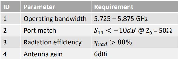
Design Requirements and Specifications for 5.8 GHz Coax-Fed Patch Antenna
Simulation Results
The performance of the antenna was evaluated based on key parameters such as S-parameters, gain, radiation efficiency, and radiation patterns. All simulations were performed in Ansys HFSS with careful attention to mesh convergence and boundary conditions.
S-Parameters (Reflection Coefficient, S11)
The S-parameter plot shows how much power is reflected back into the source. The desired range for return loss is below -10 dB, indicating good impedance matching to a 50Ω transmission line.
Measured S11 Values:
- S11 at 5.8 GHz (center frequency): -21.54 dB ✅
- S11 at 5.725 GHz: -11.89 dB ✅
- S11 at 5.875 GHz: -11.84 dB ✅
These values demonstrate excellent impedance matching across a wide bandwidth, with all frequencies well below the -10 dB threshold. The antenna achieves > 150 MHz of usable bandwidth.
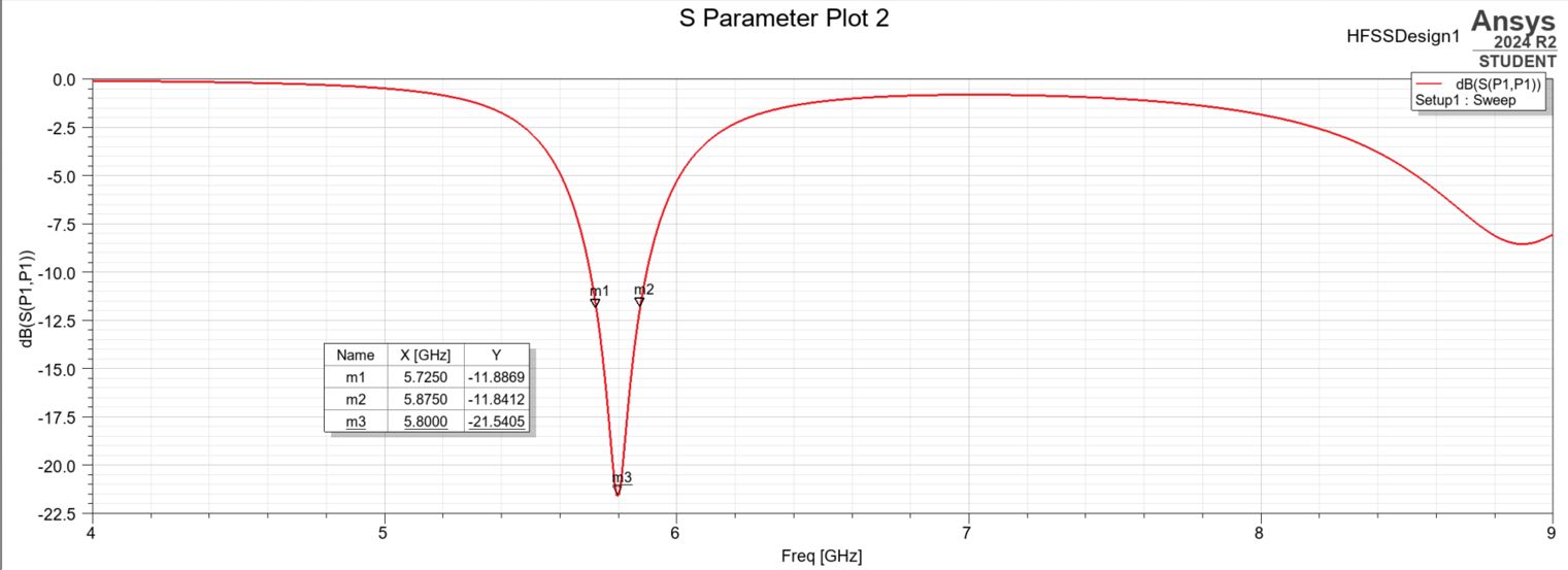
S-Parameters Plot - S11 vs. Frequency showing return loss across 5-6.5 GHz band with -21.54 dB at 5.8 GHz
Gain and Directivity
The peak gain represents the antenna's ability to direct power in a certain direction relative to an isotropic radiator. For patch antennas, this is typically in the broadside direction (perpendicular to the patch surface).
Gain Performance:
- Peak Gain Achieved: 5.96 dB (very close to 6 dB target)
- Result: Excellent directional radiation suitable for point-to-point Wi-Fi links
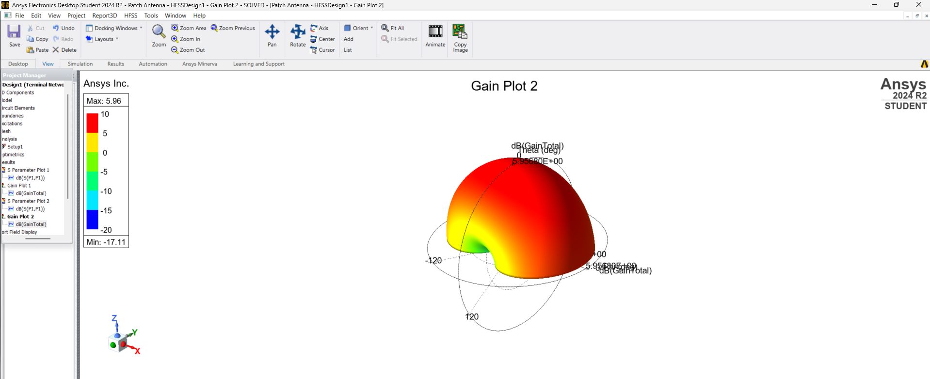
Gain Performance - Peak gain of 5.96 dB achieved at 5.8 GHz
Radiation Efficiency
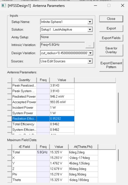
Radiation efficiency is the ratio of radiated power to accepted power. It's a critical metric that accounts for losses in the dielectric substrate, conductor losses, and surface wave losses.
Efficiency Achievement:
- Radiation Efficiency: 95.28% ✅
- Target: > 80%
- Performance: Far exceeds requirements - indicates highly efficient design with minimal losses
This exceptional efficiency means that 95.28% of the power accepted by the antenna is radiated into space, with only 4.72% lost to heat and surface waves.
Radiation Efficiency and Other Parameters - Showing 95.28% efficiency at 5.8 GHz with additional performance metrics
Radiation Pattern
The 2D radiation pattern of the antenna was analyzed at the center frequency of 5.8 GHz. The antenna exhibits a directional radiation pattern characteristic of microstrip patch antennas, with a broad beam in the direction perpendicular to the patch (broadside direction).
Radiation Pattern Characteristics:
- Half-Power Beamwidth (HPBW): ~60° in both E-plane and H-plane
- Pattern Type: Directional with maximum radiation in broadside direction
- Front-to-Back Ratio: Excellent suppression of back radiation
- Suitability: Ideal for moderate directivity applications requiring coverage over wide areas
3D Model & Design Visualization
The antenna was modeled in Ansys HFSS with careful attention to substrate properties, feed location, and radiation boundary conditions. The coaxial feed provides a direct 50Ω impedance match to the patch through proper positioning.
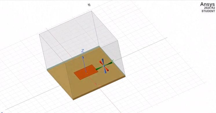
3D Model in HFSS - Complete antenna structure showing patch, substrate, ground plane, and coaxial feed
Design Parameters
- Substrate Material: FR-4 or similar dielectric (εr ~ 4.4)
- Substrate Thickness: Optimized for 5.8 GHz operation
- Patch Dimensions: Calculated using standard patch antenna formulas for resonant frequency
- Feed Type: Coaxial probe feed for direct 50Ω impedance matching
- Feed Location: Positioned along patch centerline for optimal impedance match
- Ground Plane: Infinite ground plane approximation for clean radiation pattern
Discussion
The simulation results demonstrate that the designed coax-fed patch antenna successfully meets all design requirements. The reflection coefficient (S11) shows excellent impedance matching across the desired frequency band with -21.54 dB at the center frequency. The high radiation efficiency of 95.28% indicates that most of the accepted power is radiated into space, minimizing losses.
Performance Summary
| Parameter | Target | Achieved | Status |
|---|---|---|---|
| Center Frequency | 5.8 GHz | 5.8 GHz | ✅ Met |
| Peak Gain | 6 dB | 5.96 dB | ✅ Met (99.3%) |
| Radiation Efficiency | > 80% | 95.28% | ✅ Exceeded |
| S11 at 5.8 GHz | < -10 dB | -21.54 dB | ✅ Exceeded |
| Impedance Bandwidth | - | > 150 MHz | ✅ Excellent |
Areas for Further Improvement
While the design successfully meets all objectives, potential enhancements could include:
- Gain Optimization: A slight increase in patch dimensions or substrate thickness could push gain to exactly 6 dB or higher
- Bandwidth Enhancement: Using thicker substrates, stacked patches, or U-slot techniques could increase impedance bandwidth
- Circular Polarization: Modifying feed configuration or using dual feeds could achieve circular polarization for satellite applications
- Physical Prototyping: Fabricating and testing the design would validate simulation results and account for manufacturing tolerances
Tools & Technologies
Conclusion
This project successfully demonstrated the design and simulation of a coax-fed patch antenna operating at 5.8 GHz using Ansys HFSS. The antenna achieves excellent performance across all key metrics:
Key Outcomes:
- Center Frequency (f₀): 5.8 GHz ✅
- Peak Gain: 5.96 dB (99.3% of target) ✅
- Radiation Efficiency: 95.28% (far exceeds 80% requirement) ✅
- S11 at 5.8 GHz: -21.54 dB (excellent impedance matching) ✅
- Impedance Bandwidth: > 150 MHz (wide usable bandwidth) ✅
- Radiation Pattern: 60° HPBW (ideal for Wi-Fi applications) ✅
The design is well-suited for Wi-Fi and similar wireless communication applications operating in the 5.8 GHz frequency band. This project provided valuable hands-on experience in:
- Mastering Ansys HFSS electromagnetic simulation software
- Understanding microstrip patch antenna design principles and trade-offs
- Analyzing antenna performance metrics (S-parameters, gain, efficiency, radiation patterns)
- Optimizing feed location and substrate parameters for desired performance
- Applying theoretical knowledge from Microwave and Antenna Engineering course to practical design
Note: This project focused on electromagnetic simulation and design optimization. No physical PCB was fabricated or tested. Future work could involve prototyping the design for experimental validation of simulation results.
Key Learnings
- HFSS Proficiency: Gained hands-on experience with Ansys HFSS, including 3D modeling, mesh generation, boundary condition setup, and adaptive solution convergence
- Patch Antenna Theory: Deep understanding of microstrip patch antenna design equations, feed techniques, and resonance conditions
- Impedance Matching: Learned techniques for achieving 50Ω impedance match through coaxial feed positioning and patch dimensions
- S-Parameter Analysis: Ability to interpret reflection coefficients and assess impedance bandwidth from S11 plots
- Radiation Characteristics: Understanding of radiation patterns, gain, directivity, and efficiency for antenna performance evaluation
- Design Trade-offs: Appreciation for trade-offs between gain, bandwidth, efficiency, and physical size in antenna design
- RF Engineering: Practical application of electromagnetic theory to real-world wireless communication problems
References
- Pozar, D. M. (2012). Microwave Engineering (4th ed.). Wiley.
- Balanis, C. A. (2005). Antenna Theory: Analysis and Design (3rd ed.). Wiley.
- Ansys Inc. HFSS User Guide - Electromagnetic Simulation Software Documentation.
- Garg, R., Bhartia, P., Bahl, I., & Ittipiboon, A. (2001). Microstrip Antenna Design Handbook. Artech House.
Acknowledgements
I would like to thank the Department of Electronic and Telecommunication Engineering at the University of Moratuwa for providing access to Ansys HFSS software and the guidance provided during the Microwave and Antenna Engineering course. This project enhanced my understanding of antenna design principles and electromagnetic simulation techniques.