UART Implementation on FPGA
Hardware Implementation of Universal Asynchronous Receiver-Transmitter Protocol on Intel FPGA using Verilog HDL
Project Overview
This project involves the design and implementation of a UART (Universal Asynchronous Receiver-Transmitter) communication protocol on an Intel FPGA development board. UART is one of the most widely used serial communication protocols for asynchronous data transmission between devices.
The implementation was done using Verilog HDL and tested on Intel FPGA hardware using ModelSim for simulation and Quartus Prime for synthesis and deployment. The project demonstrates fundamental digital design concepts including finite state machines, clock domain management, and serial communication protocols.
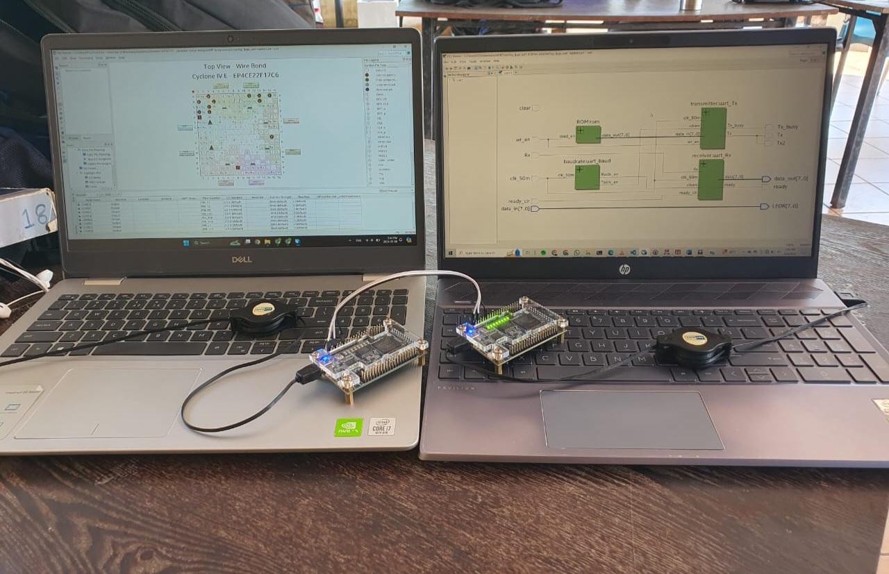
Intel FPGA development board setup with UART testing environment
Key Features
Full-Duplex Communication
Implemented both transmitter and receiver modules for simultaneous bidirectional data transfer, allowing independent transmission and reception of serial data.
Configurable Baud Rate
Designed with adjustable baud rate generator supporting standard rates (9600, 19200, 38400, 115200 bps) for flexible communication speed control.
State Machine Design
Utilized finite state machines (FSM) for both TX and RX modules to handle start bits, data bits, stop bits, and idle states efficiently.
Error Detection
Implemented parity bit checking and frame error detection to ensure reliable data transmission and identify communication errors.
Technical Implementation
UART Transmitter Module
- Idle State: TX line held high when no transmission is occurring
- Start Bit: Single low bit to indicate beginning of data frame
- Data Bits: 8-bit parallel data converted to serial format (LSB first)
- Parity Bit: Optional even/odd parity for error detection
- Stop Bit: One or two high bits to mark end of frame
UART Receiver Module
- Start Detection: Monitors RX line for falling edge to detect start bit
- Sampling: Samples data at the center of each bit period for noise immunity
- Serial-to-Parallel: Shifts received bits into 8-bit register
- Validation: Checks parity and stop bits to verify frame integrity
- Data Ready: Generates flag signal when valid byte is received
Baud Rate Generator
- Clock Divider: Derives required baud rate from system clock (50 MHz)
- Oversampling: Generates sampling clock at 16x baud rate for accurate bit detection
- Counter Logic: Uses modulo counters to generate precise timing signals
Development Tools & Methodology
Hardware Platform
- FPGA Board: Intel Cyclone IV/V FPGA development board
- System Clock: 50 MHz onboard oscillator
- I/O Interfaces: GPIO pins configured for UART TX/RX signals
- Testing: Connected to PC via USB-to-UART adapter for verification
Software Tools
- Quartus Prime: Intel FPGA design software for synthesis, place & route, and programming
- ModelSim: HDL simulator for functional verification and timing analysis
- Verilog HDL: Hardware description language for RTL design
- Terminal Software: Serial terminal (PuTTY/Tera Term) for communication testing
Testing & Verification
- Simulation: Comprehensive testbenches in ModelSim to verify TX and RX operations
- Waveform Analysis: Examined timing diagrams to ensure correct bit timing and framing
- Hardware Testing: Transmitted and received data between FPGA and PC terminal
- Loopback Test: Connected TX to RX for self-testing and debugging
Learning Outcomes
- Hands-on experience with FPGA development workflow from RTL design to hardware deployment
- Understanding of serial communication protocols and asynchronous data transmission
- Practical implementation of finite state machines in hardware
- Clock domain management and timing constraints in digital design
- Verilog HDL coding practices and synthesizable design techniques
- Hardware simulation and verification methodologies
- FPGA synthesis, place & route, and bitstream generation
- Debugging techniques for hardware implementations